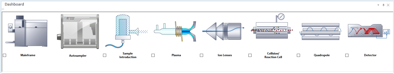
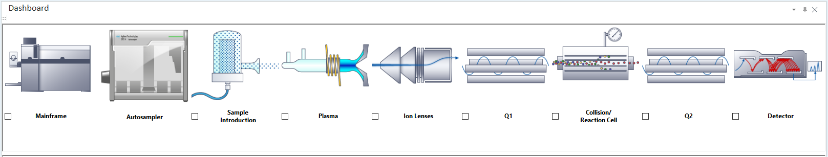
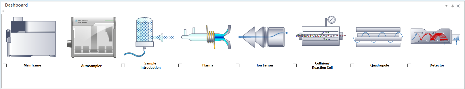
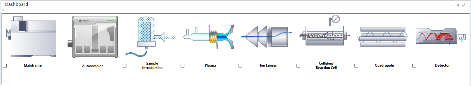
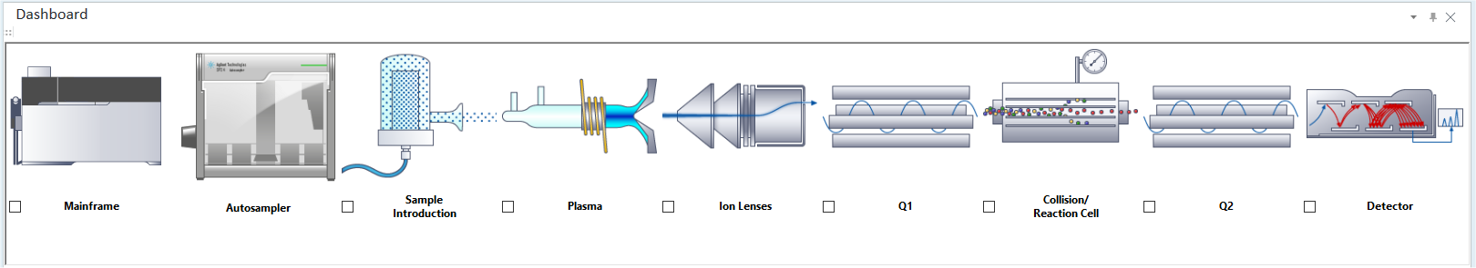
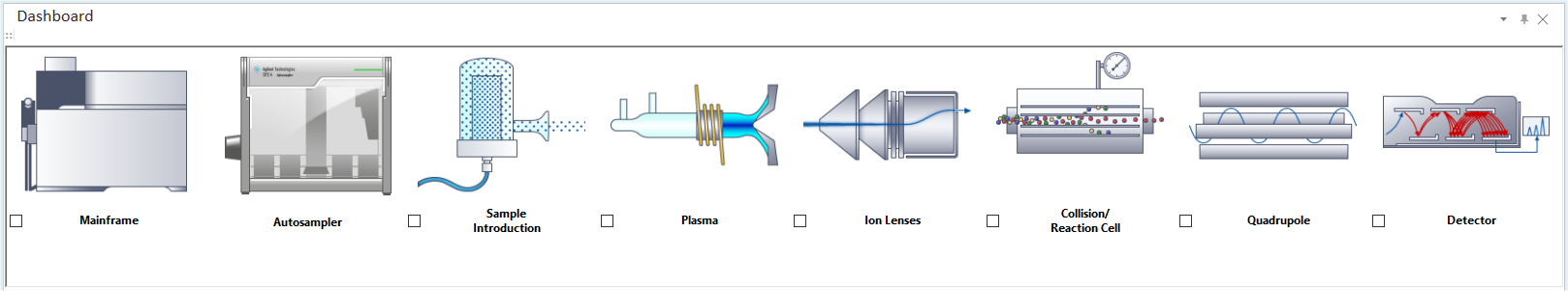
Dashboard Pane
This section describes the functions in the Dashboard pane.
- Title Bar
- Mainframe
- ADS 2
- Autosampler
- Agilent LC
- Agilent GC
- 3rd party peripheral
- Sample Introduction
- Plasma
- Ion Lenses
- Collision/Reaction Cell
- Quadrupole
- Q1 and Q2
- Detector
- To Get Here
Title Bar
The title bar buttons and the context menu have the same functions as the Title Bar of the Instrument Status Pane.
Mainframe
Context Menu
Right-click on the illustration to display the context menu.
[Properties]
Mainframe from the [Settigns] dialog box appears.
[Vacuum]
Turns the vacuum pump on/off.
[Early Maintenance Feedback]
Opens the Early Maintenance Feedback Pane, which allows you to set maintenance items and their maintenance periods in advance. When the maintenance time is reached, a message can be displayed to tell you the maintenance time, measured by the accumulated time of the plasma ON state or vacuum operation.
[Performance Report]
The Performance Report Pane is displayed. It shows the result of the performance measurement, current instrument status, tune parameter values, and meter values.
[Maintenance Log]
The Maintenance Log Pane is displayed. It shows the name of the operator who performed the maintenance and the maintenance details.
[Communication]
The [Set Communication] dialog box appears, which lets you set the online/offline setting and IP address.
[Instrument Information]
The [Set Instrument Information] dialog box appears, which lets you check or enter the model name of the instrument.
[Conditioning Settings]
This item is displayed when [Enable Enhanced Stability Tune Mode] is selected in [Options] category in the [Settings] dialog box.
Opens the [Conditioning settings] dialog box. In this dialog, the sample type which can be used for the parameters in conditioning can be set.
[External Device]
Opens the [External Device Connection] dialog box where you can configure settings for connecting MassHunter to an external device.
ADS 2
This item is displayed when [ADS 2] is selected for Sample Introduction.
Context Menu
[Properties]
[ADS 2] from the [Settings] dialog box is displayed.
[Initialize]
Reset the ADS 2 by sending the syringes home and setting the valves to uptake. Execute after startup is complete.
[Flush]
In the [Set number of flushings] dialog box, enter the number of flushings and click [OK].
Empty and refill the syringes, send solution through the tubing, rinse out any contamination, and then fill the syringes with fresh diluent and carrier.
[Change Syringe]
Fill the syringes with air. The syringes will then push the air through the tubing and remove as much solution from the tubing as possible so that the user can safely change the plumbing or the syringes.
[Prime]
Perform resetting and initialization and then move on to the Flushing state to perform the rest of the operations so that the user can restore ADS 2, which has aborted a sequence or is in an error state.
[Show Flow Path Diagram]
The [Flow Path Diagram] dialog box is displayed. This displays graphics of the solution flow, valves, and syringe positions.
[System Test]
The [ADS 2 System Test Configuration] dialog box is displayed. After setting the conditions and clicking [OK], a batch for system testing is created, automatically added to the queue, and acquisition begins. Once the acquisition is complete, the test results are displayed.
AVS
This item is displayed when [AVS] is selected for Sample Introduction.
Context Menu
[Properties]
[AVS] from the [Settings] dialog box appears.
[System Test]
[AVS System Test Configuration] dialog box appears. After setting the conditions and clicking [OK], a batch for system testing is created. Once the acquisition is complete, the test results are displayed.
Autosampler
The term "ALS" has been changed to "Autosampler" in MassHunter 4.4.
This item is displayed when the [Use Autosampler] check box is selected in the Sample Introduction in the [Settings] dialog box.
Context Menu
Right-click on the illustration to display the context menu.
[Properties]
The [Configure Autosampler] dialog box is appears.
[Set Communication]
The [Set Autosampler Communication] dialog box is displayed, which lets you set the COM port to which the communication cable for the autosampler is connected.
[Set Probe Depth]
When [EXR-8/XLR-860] is selected for [Autosampler Type], the [Configure Probe Depth] dialog box is displayed. This allows you to set the probe depth.
[Set Sampling Depth of I-AS]
When [I-AS] is selected for [Autosampler Type], the [Set Sampling Depth of I-AS] dialog box is displayed, which lets you set the sampling depth.
[Escape Mode]
This item is displayed when [I-AS] is selected for [Autosampler Type].
Mark to enter the ESC (escape) Mode. In escape mode, to move the probe over the sample tray, the sample tray is rotated to a pre-determined position before the probe is moved. The position of the probe in escape mode is the last (highest) sample number on the inner radius of the sample tray, as shown in the following table. Samples in this row cannot be measured in escape mode.
Tray Type |
Location of Vial Not Measured in Escape Mode |
|---|---|
89-Vial Sample Trays (Types A, D, E) |
32, 57, 77, 89 |
53-Vial Sample Tray (Type B) |
25, 41, 53 |
28-Vial Sample Tray (Type G) |
22, 28 |
18-Vial Sample Tray (Type C) |
12, 18 |
Agilent LC
This item is displayed when [Agilent LC] is selected for Sample Introduction.
When you set Agilent LC as the Sample Introduction, be sure to click [Update Module]. You may not be able to run other tasks until the module update completes.
If you replace it with another sample introduction after you set Agilent LC as the Sample Introduction, be sure to remove the APG remote cable from the instrument.
Context Menu
[Instrument Configuration]
The [Instrument Configuration] dialog box is displayed, which lets you configure the settings for the Agilent LC.
[Auto Config]
The [Auto Config] dialog box is displayed.
Enter the IP address or host name of the LC. The setting is shown in each module of the LC.
[Device Configuration]
The setup table is displayed in the pane, which lets you configure settings of Agilent LC.
Setup Table
For more information about each item, see the Agilent LC product documentation.
[Update Module]
Set the information for Agilent LC to MassHunter.
When you set Agilent LC as the Sample Introduction, be sure to click this button. You may not be able to run other tasks until the module update completes.
For information about the steps in an analysis when the LC is connected, refer to LC (non cap-LC) Analysis under Non-standard Configurations in the reference section of this Help
Agilent GC
This item is displayed when [Agilent GC] is selected for Sample Introduction.
Before connecting the Agilent GC, run the batch file (\G7201D\GCSettings.bat) in the ICP-MS MassHunter Workstation System Disc.
When you set Agilent GC as the Sample Introduction, be sure to click [Update Module]. You may not be able to run other tasks until the module update completes.
If you replace it with another sample introduction after you set Agilent GC as the Sample Introduction, be sure to remove the APG remote cable from the instrument.
If any parameters are changed using the hardware buttons on the GC, follow the steps below to reflect the new parameters in ICP-MS MassHunter:
Close and then re-open Instrument Control.
Click the [Get GC Configuration] button from the Hardware task > Agilent GC > Connection tab.
Click the [Update Modules] button on the toolbar.
Context Menu
[Instrument Configuration]
The [Instrument Configuration] dialog box is displayed, which lets you configure the settings for the Agilent GC.
[Auto Config]
The [Auto Config] dialog box is displayed.
Enter the IP address or host name of the GC. The setting is shown in each module of the GC.
[Device Configuration]
The setup table is displayed in the pane, which lets you configure settings of Agilent GC.
Setup Table
For more information about each item, refer to the product documentation supplied with Agilent GC.
[Update Module]
Set the information for Agilent GC to MassHunter.
When you set Agilent GC as the Sample Introduction, be sure to click this button. You may not be able to run other tasks until the module update completes.
If you replace it with another sample introduction after you set Agilent GC as the Sample Introduction, be sure to remove the APG remote cable from the instrument.
The GC functions [Skip to the next sample] and [Pause for user interaction] are not available when using GC-ICP-MS.
3rd party peripheral
This item is displayed when a third-party peripheral is selected as the [Sample Introduction].
When you set a third-party peripheral as the Sample Introduction, be sure to click [Update Module]. You may not be able to run other tasks until the module update completes.
Context Menu
The setup table is displayed in the [Device Configuration] pane, which lets you configure settings of 3rd party peripherals.
[Device Configuration]
The setup table is displayed in the pane. This allows you to configure the settings of the third-party peripheral.
Setup Table
For more information about each item, refer to the product documentation supplied with the third-party peripheral.
[Update Module]
Set the information for 3rd party peripheral to MassHunter.
When you set a 3rd party peripheral as the Sample Introduction, be sure to click this button. You may not be able to run other tasks until the module update completes.
Sample Introduction
Lets you configure the settings for the sample introduction, check the nebulizer, and adjust the torch axis.
Context Menu
Right-click on the illustration to display the context menu.
[Properties]
Sample Introduction from the [Settings] dialog box appears.
[Nebulizer Test]
The Nebulizer Test Pane is displayed, which checks whether the nebulizer pressure is in the appropriate range. Note however that if [Other] is specified for Nebulizer, this item is not performed.
[Post PeriPump Rotation]
If the peripump is stopped for a long time, the pump tubing may be damaged. To avoid this damage, when the plasma is OFF, the peripump can be rotated periodically.
Mark this check box to enable the periodical peripump rotation. Clear the check box to disable the function.
[SC Cooling]
This allows customers using 3rd party spraychambers, for example the ESI cyclone or Niagara Seaspray, to use Agilent PeriPump etc but not Agilent spraychamber. Even if this is disconnected when using an Agilent peltier cooler using this function, no error message is displayed. The default value is on. If this is not selected, SC cooling is not performed.
[Maintenance]
Opens the [Sample Introduction Maintenance] dialog box that is used for the maintenance of the sample introduction area.
[Special Process for Sample Change]
The [Set Special Process for Sample Change] dialog box is displayed, which lets you set the special action while the probe of the autosampler is moving.
[Remote Signal Settings]
This menu item is displayed when [LA] or [other] is selected from the [Sample Introduction] list. Selecting this item opens the [Remote Signal Setting] dialog box.
[Configure Devices]
Displays the dialog box for configuring the installed external device.
[AVS Configuration]
Opens the [Set ISIS Configuration] dialog box. Specify the number of pumps and whether to use the valve when you use ISIS 2 for sample introduction.
However, [Autodilution] cannot be selected in MassHunter 5.3 or later.
Plasma
Lets you perform Plasma Correction or change the plasma ignition mode.
Context Menu
Right-click on the illustration to display the context menu.
[Properties]
Plasma from the [Settings] dialog box is displayed.
[Torch Axis Setting]
The Torch Axis Setting Pane is displayed, which lets you adjust the horizontal and vertical positions of the torch axis.
[Plasma Correction]
The Plasma Correction Pane Table is displayed, which lets you perform the plasma correction.
"Plasma Correction" is required after maintenance/replacing torches or sampling cones. These correction values are used to determine the tune parameters.
In the following cases, plasma correction can be performed.
Ion Lenses is [x-Lens] and Nebulizer is [MicroMist] or [Mira Mist].
Ion Lenses is [s-Lens] and Nebulizer is [MicroMist] or [Micro Flow(100)].
Ion Lenses is [m-Lens] and Nebulizer is [Micro Flow(200)].
[Gas Purge at Standby]
Displays the Gas Purge Setting Pane. To reduce the background-equivalent concentration (BEC) of silicone (Si) and sulfur (S), purge the Ar gas line during standby.
[Auto RF Matching]
Starts the automatic adjustment of RF matching.
Use this to perform primary RF Matching (such as for inclusion in a batch created from a Preset Method or Blank Template) only. In all other cases (creating of batch from a Preset Method or an Existing Batch) do RF matching, as required, at the time of batch creation.
When the cool plasma mode is used, organic solvents are analyzed, or the torch is replaced, use this function to adjust the RF matching. This helps to stabilize the plasma ignition and enhance the sensitivity.
[Plasma Cleaning]
Plasma cleaning is used to clean the surface of the Extract 1 lens (s-lens) by exposing it to the plasma. This function is effective in Standby mode, with the skimmer removed. When this function is selected, the plasma is ignited and stays on for a minute.
The plasma cleaning function is part of a complete procedure for cleaning the skimmer and lenses; using it alone is not recommended. For the cleaning procedure, please contact your Agilent Application Engineer.
Ion Lenses
Lets you check the ion lens connection.
Context Menu
Right-click on the illustration to display the context menu.
[Properties]
Ion Lenses from the [Settings] dialog box is displayed.
When using a c-lens, select s-lens as the lens configuration.
[Maintenance]
Opens the Ion Lenses Maintenance Pane to test the status of the ion lens wiring.
Collision/Reaction Cell
Lets you configure the cell gas line and perform the Leakage Check.
Context Menu
Right-click on the illustration to display the context menu.
[Properties]
Cell from the [Settings] dialog box is displayed.
[Maintenance]
Opens the Cell Maintenance Pane that lets you set the flow rate of each gas and perform the purging and vacuuming of the cell gas line.
[Run H2 gas Stop Valve Leakage Check]
This item is displayed when the H2 gas line is connected. If you select this item, the "Start H2 gas Stop Valve Leakage Check?" message is displayed. Click [Yes] to start the Leakage Check for valve. When the check is completed, either "No leak found." or "Leak found. Please check connection." message is displayed.
[Run 3rd Cell Gas Stop Valve Leakage Check]
This item is displayed when the 3rd Cell Gas line is connected. If you select this item, the "Start 3rd cell gas stop valve leak check?" message is displayed. Click [Yes] to start the Leakage Check for valve. When the check is completed, either "No leak found." or "Leak found. Please check connection." message is displayed.
[Run 4th Cell Gas Shutoff Valve Leakage Check]
This item is displayed when the 4th Cell Gas line is connected. If you select this item, the "Start 4th cell gas shutoff valve leak check?" message is displayed. Click [Yes] to start the Leakage Check for valve. When the check is completed, the message "No leak found." or "Leak found. Please check connection." is displayed.
Quadrupole
Adjusts Resolution / Axis Setting automatically.
Q1 and Q2
Automatically adjust the resolution/mass axis of a quadrupole.
"Q1" and "Q2" represent the front quadrupole and rear quadrupole, respectively.
Context Menu
Right-click on the illustration to display the context menu.
[Properties]
Quadrupole from the [Settings] dialog box is displayed.
[Resolution / Axis Setting]
The Resolution / Axis Setting Pane is displayed and lets you adjust the AMU Gain, AMU Offset, Axis Gain, and Axis Offset.
Detector
Configure the settings for the detector.
Context Menu
Right-click on the illustration to display the context menu.
[Properties]
Detector from the [Settings] dialog box is displayed.
[P/A Factor Setting]
The P/A Factor Setting Pane is displayed and the P/A Factor is automatically adjusted.
[EM Setting]
The EM Setting Pane is displayed and the EM is automatically adjusted.
[Dead Time Calibration]
This menu item is enabled when [Dead Time Calibration] selected in [Options] category in the [Settings] dialog box. The Dead Time Calibration Pane is displayed and the Dead Time Calibration is performed.
[Auto Integration Time Setting in Analog Mode]
If this item is ON, the dwell time in analog mode for the spectrum acquisition is set at its minimum of 100 microseconds. This protects the detector from counting large signals for long time as a precaution. This function is not available for some models.
[Prohibited Masses]
The [Set Prohibited Masses] dialog box is displayed, which lets you change the prohibited masses. Usually, do not change them.
To Get Here
- Click [Dashboard] from the [Hardware] group in the Task Navigator.